RAM expansion to 512K with SRAM

There are two methods to upgrade RAM on Pentagon-128: by replacing memory chips RU5 (4164) to RU7 (41256) or by connecting single SIMM 30/72 pin module. This expansion however differs from the other two by using only one SRAM memory chip with few other logic chips, this simplifies the work that needs to be done, lowers power consumption and doesn’t require track cutting on computer board. I measured power consumption (without VG93 and AY): with RU5 – 830mA, with SRAM – 610mA.
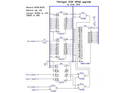
Schematic is shown in the picture below:
Before you do any assembling, several modifications needs to be done:
- remove all RU5 chips from the board; if they’re soldered – desolder/cut them out and solder sockets in their place;
- remove capacitor C16;
- connect chip DD61 pin 14 to +5V, pin 13 to GND. Pin 12 will be needed to connect to expansion schematic as shown. Pins 12, 13 and 14 by default are not connected anywhere, so this mod will not alter operation of your computer even when using standard RU5 chips.
And that’s it, no other mods required!
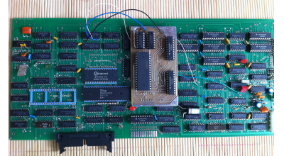
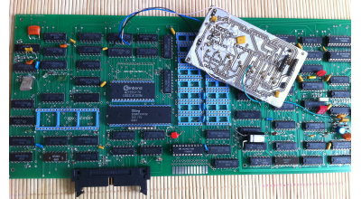
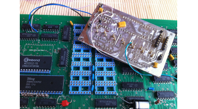
You can solder everything on a stripboard or make yourself a double sided PCB with toner transfer method (you will find all project files at the bottom of this page in zip archive). Then connect all pins to signals R1-R8, D0-D7, Q0-Q7, C16, C37, C38, +5V, GND and put your board in computer’s RAM sockets as shown in photo. Be aware that by default chips DD27 and DD35 on most Pentagon-128 computers are shifted to one side by 1,27mm, so if you’ll be using a stripboard with 2,54mm hole spacing it might not fit. For pins you can use male-male SIP pins or simple resistor or capacitor legs. However, gold plated pins are preferred here for a better contact. After you put your expansion board in place, connect five wires to the dedicated chip pins on Pentagon board as show in schematic. Resistor R1 – smd type 1206 or 0805 is placed on the bottom along with RAS signal wire nearby.
When everything is properly assembled and connected it should work without any adjustments. Recommended logic chips are 74HC or 74HCT. You may also use 74LS series chips (tested). More faster series like 74ALS/AC/ACT are not needed here, unless you plan to run your Pentagon in turbo mode, but you should test this yourself. For SRAM you can use any 512kbit x 8bit chip in DIP32 enclosure with 55 or 70ns latency. I used BS62LV4006PIP55. C1 decoupling capacitor is required with capacity of at least 0.1uF as close as possible to SRAM power supply pins (16 and 32). I recommend at least 1uF multilayer ceramic cap i.e. X7R. It is also recommended to use 0.1uF decoupling caps on DD3 and DD4 chips.
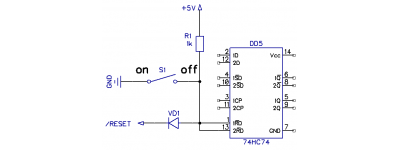
It is possible that after this upgrade some of your programs will no longer work correctly with 512K of RAM. For example, demo “Rage” will hang right at the start. To fix this you can use a switch as shown in the picture below to disable memory over 128K as needed:
You can test all 512K with system test program like System Test v4.30r or use a special RAM test programmed in ROM (check the archive at the bottom).
With this method you can expand your RAM up to 1MB in Pentagon-1024 standard with a 1Mbit x 8bit memory chip. In that case you will need additional HC08/HCT08 logic element to control the upper address line A19 and use #7FFD port’s (DD62 chip) 5th bit. But this will need to be modified (read more about it here in Russian language http://zxdn.narod.ru/hardware/dv07pn1m.htm).
Pentagonas with 512K SRAM looks like this:
Project files:
- RAM test in ROM: ram_test.zip
- DipTrace project files: diptrace-pcb-sch.zip
Author Hysk 2015-04-29
Last modified: 2015-05-11 21:35:11
